Capability Modeling Guidelines | How to Structure a Capability Map
Create a Two-Dimensional Layout
A Capability Map is a two-dimensional, one-page, high-level representation of the entire enterprise's capabilities. It should serve as the single master structure, accepted by all co-creators and recognised across the enterprise. This requires careful attention both to a clear logical structure (as described in previous sections) and to the graphical layout.
Use the X and Y axes thoughtfully to:
- make categories clear
- make major product groups visible
- express the relationships between capabilities
- belongs together
- follows (sequences of capabilities in time)
- dependencies of capabilities
Capability categories
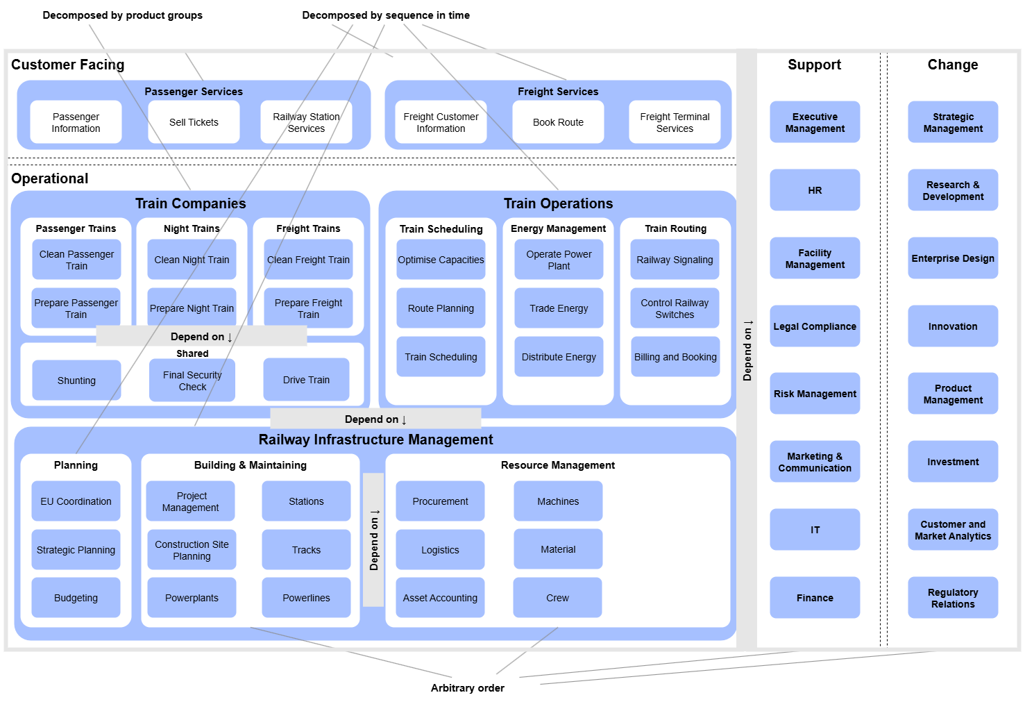
Place customer-facing capabilities in the top-left area and operational capabilities below them. Arrange support and change capabilities to the right. This layout creates a projector-friendly, landscape (16:9) view.
Belongs together
Group related capabilities that together form a higher-level capability within a single box.
Follows (sequence in time)
You can use either axis to indicate that capability B is typically performed after capability A. For example, use the X-axis to position Capability A to the left of Capability B.
Dependencies
The Y-axis is often used to show that one [capability] depends on another. Position capability A above capability B to indicate that Capability A relies on the outputs of Capability B.
Practical Tips
Don’t overwhelm people.
Appealing landscape layout.
Find reasonable compromises in expressing dependencies.
Example: Intersection Railways
The following example illustrates the recommended guidelines for designing a Capability Map layout:
